H SPLIT CONCENTRIC
Split concentric cables are predominantly used by Distribution Network Operators (DNO’s) when providing the final service connection to domestic properties. Split concentric cables are also suitable for sub main distribution and have been found to be particularly useful within high rise buildings and street lighting systems.
These cables are designed to be installed in air, or for burial in free draining soil conditions
- Manufactured to BS 4553-1 Table 3
- The neutrals and bare earth wires are laid in a concentric layer around the insulated phase conductor with PVC string separators separating the neutral and earths. This is then bound with a clear polyester tape and then PVC sheathed.
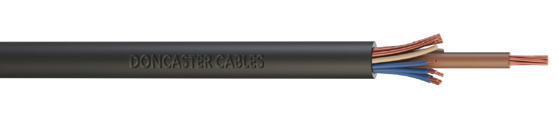
Available Variations
| Name | Core Colours | Current Ratings | Weight | Standard | Colour | Bullet1 | Bullet2 | Bullet3 | Details |
|---|---|---|---|---|---|---|---|---|---|
| H SPLIT CONCENTRIC 16.0 | Brown phase, blue neutrals | 97 amps | 652.49 | BS 4553-1 | Black | Manufactured in the UK | Manufactured with 100% renewable energy | Uses materials and manufacturing techniques designed to make the electricians life easier | View |
| H SPLIT CONCENTRIC 25.0 | Brown phase, blue neutrals | 130 amps | 844.65 | BS 4553-1 | Black | Manufactured in the UK | Manufactured with 100% renewable energy | Uses materials and manufacturing techniques designed to make the electricians life easier | View |
| H SPLIT CONCENTRIC 4.0 | Brown phase, blue neutrals | 42 amps | 207.02 | BS 4553-1 | Black | Manufactured in the UK | Manufactured with 100% renewable energy | Uses materials and manufacturing techniques designed to make the electricians life easier | View |
| H SPLIT CONCENTRIC 6.0 | Brown phase, blue neutrals | 54 amps | 290.01 | BS 4553-1 | Black | Manufactured in the UK | Manufactured with 100% renewable energy | Uses materials and manufacturing techniques designed to make the electricians life easier | View |
Dimensional Details
| Product Code | HSPLITCON4.0 | HSPLITCON6.0 | HSPLITCON710 | HSPLITCON716 | HSPLITCON725 |
| Nominal CSA of Phase Conductor (mm²) | 4.0 | 6.0 | 10.0 | 16.0 | 25.0 |
| Nominal Makeup of Phase Conductor (mm) | 7/0.85 | 7/1.04 | 7/1.35 | 7/1.70 | 7/2.14 |
| Approx Combined CSA of Neutrals (mm²) | 4.0 | 6.0 | 10.0 | 16.0 | 25.0 |
| Nominal Makeup of Neutrals (mm) | 7 x 0.85 | 7 x 1.04 | 7 x 1.35 | 7 x 1.70 | 11 x 1.70 |
| Nominal Combined CSA of Earth (mm²) | 4 | 6.0 | 10.0 | 16.0 | 16.0 |
| Nominal Makeup of Earth (mm) | 3 x 1.35 | 4 x 1.53 | 4 x 1.78 | 4 x 2.25 | 4 x 2.25 |
| Nominal Radial Thickness of Insulation (mm) | 0.8 | 0.8 | 1.0 | 1.0 | 1.2 |
| Nominal Radial Thickness of Sheath (mm) | 1.4 | 1.4 | 1.4 | 1.4 | 1.5 |
| Approximate Overall Diameter (mm) | 9.8 | 11.2 | 12.6 | 15.0 | 18.3 |
| Approximate Weight (kg/km) | 207 | 291 | 403 | 656 | 848 |
| Weight and dimensional information is provided as an approximate guide only. | |||||
| Phase Conductor Size (mm²) | Current Rating | Approx Voltage Drop | |||
| In air (A) | In Ground (B) | ||||
| 4 | 42 | 53 | 11 | ||
| 6 | 54 | 66 | 7.2 | ||
| 10 | 74 | 88 | 4.3 | ||
| 16 | 97 | 115 | 2.7 | ||
| 25 | 130 | 150 | 1.7 | ||
| Phase Conductor Size (mm²) | 4 | 6 | 10 | 16 | 25 |
| PHASE Maximum d.c Conductor Resistance at 20ºC (ohm/km) | 4.61 | 3.2 | 1.9 | 1.2 | 0.727 |
| NEUTRAL Maximum d.c Conductor Resistance at 20ºC (ohm/km) | 4.8 | 3.2 | 1.9 | 1.2 | 0.76 |
| EARTH Maximum d.c Conductor Resistance at 20ºC (ohm/km) | 4.8 | 3.2 | 1.9 | 1.2 | 1.2 |